Case Studies

BioMedical Device Design Optimization
Metered dose inhalers (MDIs) are widely used for the treatment of lung diseases, such as asthma. The delivery of the drug to the lung can be as low as 5% of the metered dose. In order to maximize the dose, a patient needs to inhale whilst simultaneously actuating the inhaler, which can be difficult. Spacers have been developed to solve these drawbacks, and increase drug delivery to the lungs. However, there continues to be significant room for improvement.
FTS Engineering Answers has been investigating the parameters of most influence of drug delivery (the atomized droplet size distribution and the spacer geometry) using transient, multiphase CFD simulations.
The majority of the mass of the metered dose is an accelerant, typically HFA134, which provides the energy to atomize the spray. Detailed properties of the accelerant and the drug as well as multiphase heat and mass transfer are required in order to capture these physics correctly.
These physics are combined with detailed geometrical models of a range of spacer devices and design options (position of vents, valve position and design etc.) to quantify the effect of each change on the drug delivery.

Focus on Motor Cooling
FTS Engineering Answers is regularly asked to provide insight into the effectiveness of the cooling of electric motors particularly for the overall packaging of the motor within the electric machine, and to optimize the cooling design of electric motors.
Cooling the motor aims to maximise the motor efficiency by reducing temperature losses; allows for the potential of higher power density leading to weight and size reduction; and increases machine reliability by decreasing the operating temperatures. Design of motors is typically carried out in 2D motor design software. These capture the temperature dependent physics, but are limited in the 3D effects around the stator end windings.
FTS Engineering Answers has developed CFD modelling approaches for three methods of cooling:
- Air cooling
- Water cooling
- Oil Cooling
For all of these methods, the underlying temperature dependent physics are incorporated from the motor design software, and then the cooling is carried out in 3D CFD software, which captures the 3D effects around the stator end windings.
Air Cooling

Air cooling is the simplest form of cooling. In the example, there is forced convection over the motor; the heat that’s generated within the motor is transferred to the housing and convected away from the device via the cooling fins or conducted away via a heat sink.
Key engineering challenges are the effectiveness of the cooling within the overall packaging and the optimization of the cooling fin arrangements.
Water Cooling
Typically, a water/glycol mix is pumped through a series of channels in the motor’s housing. This approach is typical of larger automotive motors, because the approach is simple and robust, and the motor can be easily sealed. However, it leads to an increase in packaging of the motor. The cooling is indirect so the thermal inertia associated with the heat transfer from the hot stator windings to the cold water jacket can lead to reduced performance. Additionally, the cooling of the rotor is not as effective as the cooling of the stator. Key engineering challenges are the effectiveness and optimization of the cooling channels within the motor housing.
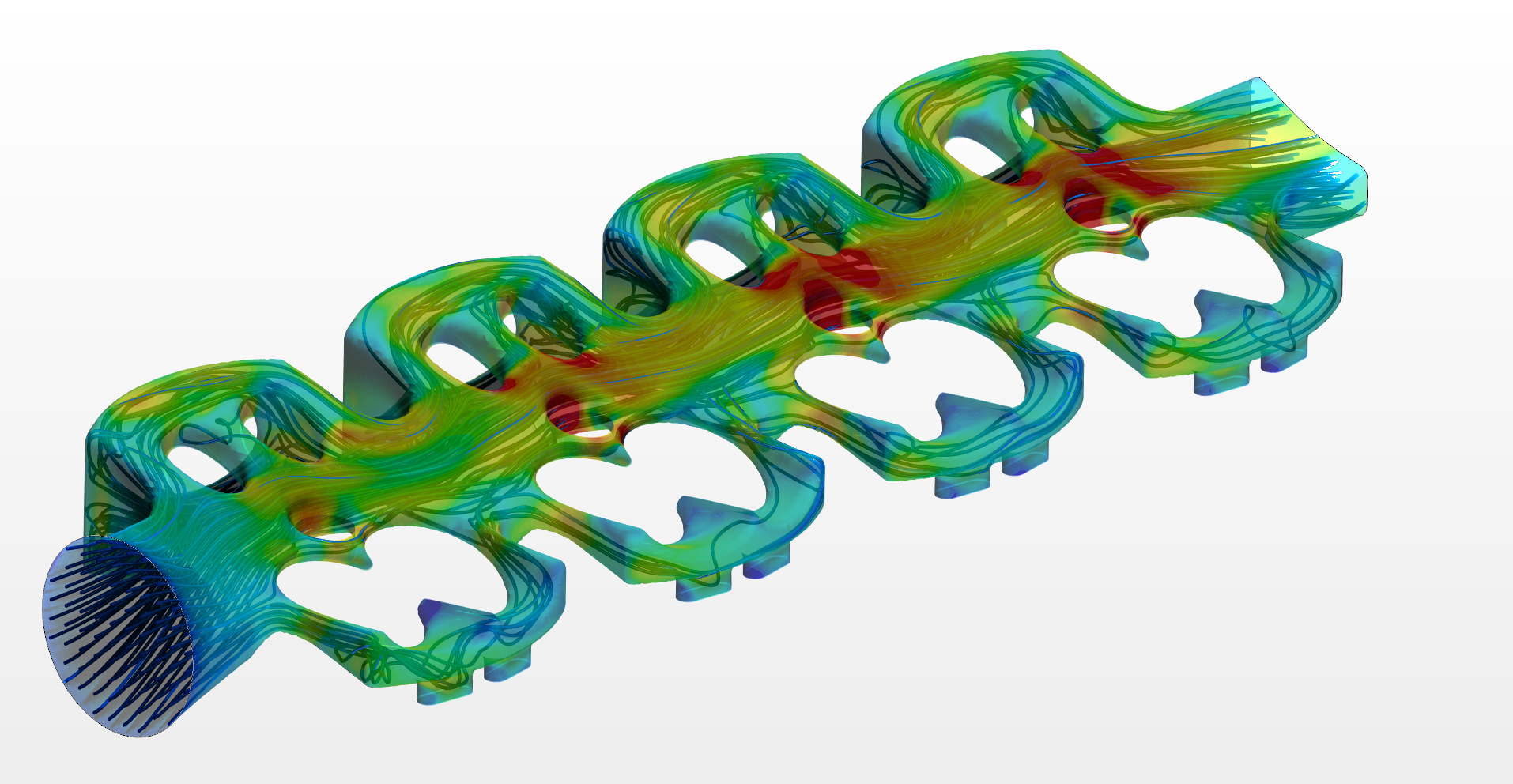
Oil Cooling of the Stator Windings Directly
In contrast to the indirect water cooling, here jets of oil are aimed directly on to the stator windings. The oil is injected via a series of high pressure nozzles, and after the oil is injected it must be drained and cooled and can then be recycled. The challenges of this approach are the arrangements for the high pressure nozzles; ensuring that the oil coverage of the windings is as uniform as possible to give even cooling; and the incorporation of oil outlets to drain the oil effectively. The major benefit of the approach is achieving very high convective heat transfer coefficients.
Key engineering challenges are the effectiveness and optimization of the oil cooling jets in ensuring uniform coverage of the windings and the drainage of the oil from the motor.
Contact FTS Engineering Answers to discuss your Motor Cooling questions!
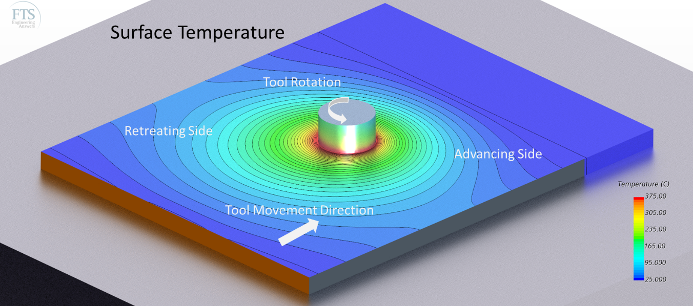
Friction Stir Welding
Friction welding processes use the heat generated between contacting surfaces that are in relative motion and pressed together to generate hot and clean surfaces to produce a joint. Rotary Friction Welding (RFW) joins two cylindrical cross sections using a relative rotational motion followed by compression of the cylinders. The most recent friction welding process uses a non-consumable rotating pin to produce heat between adjacent flat surfaces. This is called Friction Stir Welding (FSW).
Background
FTS Engineering Answers Ltd and Transforming Stress Ltd (both founder members of OxCam Engineering Arc) have been developing CFD based methods to model FSW such that it can be easily implemented for a wide range of applications. This approach does not require fudge factors from test welds or extensive data sets for material behaviour and has been validated over a wide range of welding conditions.
It is important that original joint line is mixed and compressed by the FSW tool during welding, whilst keeping workpiece temperature controlled to avoid the generation of flash at the edge of the workpiece shoulder. Optimised welding procedures can be developed by welding trials, but there are significant advantages associated with the use of an accurate computer model to develop robust welding procedures.
Outcomes
A computer model of FSW can be used to make sensitivity studies of tool shapes before welding trials and to investigate the effect of variations in workpiece properties that may not be possible in a small welding trial. The methods developed by Oxcam Engineering Arc can be used in a straightforward manner to reduce the costs associated with the implementation of FSW within the requirements of new industrial applications.
We are able to support our clients with these manufacturing activities and more, contact FTS Engineering Answers to discuss your questions!

Processing of CT and MRI Scans
The objective of the study was to demonstrate the process of taking a Medical Scan (either CT or MRI) extracting physical parts of the scan (in this case the carotid arteries) and carry out a simulation with that geometry.
Process
Using an open source tool (3D Slicer), the CT Scan was segmented to extract the carotid arteries. The segmented carotid arteries are then exported from 3D Slicer and imported into STAR-CCM+ as stl files.
Simulation
A Fluid Structure Interaction Simulation is then set up within STAR-CCM+. Appropriate boundary conditions are applied. A pulse flow rate at the inlet and a series of windkessel models at the outlets. Material properties are applied to the artery walls, and a pseudo “neck” is added around the artery to give the damping effect the neck does in reality.
We are able to support our clients with converting CT/MRI data to simulations, ensure sensible simulation set up and carry out FSI simulations; contact FTS Engineering Answers to discuss your questions!
Engine Thermal Management
An engine cooling system must work to manage the thermal behaviour of the engine without allowing an individual part to overheat; if one part fails the whole engine will fail.
The engine is exposed to both high-cycle fatigue and low-cycle fatigue. High-cycle fatigue due to the normal engine combustion cycle and low-cycle fatigue due to the repetitive cycle of engine heat up, operate at high temperature and then cool down when the engine is switched off. Additionally, some regions of the engine are exposed to temperature hot spots and high temperature gradients, in particular the water jacket in the cylinder head above the dome.
It is therefore vital that the cooling system works effectively and efficiently.
Working with our Clients FTS Engineering Answers has built expertise of Engine thermal management, where we build conjugate heat transfer models, explicitly modelling the Cylinder head, valves, valve guides, valve seats, Engine Block, Pistons, Piston rings and their contacts, and the cooling jacket in both the head and the block. These provide in depth analysis and accurate insight of the temperature distribution throughout the engine. Subsequently, the thermal stress can be calculated and the design options evaluated, and with the application of different engine cycles both low and high cycle fatigue can be investigated providing insight into the reason for failures.
We are able to support our clients with a wide range of Heat Transfer activities, contact FTS Engineering Answers to discuss your questions!

Investigation of cornea graft failure following DMEK surgery
One option for corneal transplants is DMEK (Descemet Membrane Endothelial Keratoplasty). The procedure is outlined here. As described, once the replacement cornea is unrolled and positioned in the anterior chamber of the eye, SF6 or Air is injected below the cornea graft to push it up to the graft site. SF6 or Air is then left in the chamber until it is naturally replaced by the aqueous fluid of the eye. This takes a few days.
During the recovery period the patient is instructed to lie down for longer periods especially in the immediate period after surgery. Following this period the patient is allowed to move freely. It is known that some grafts peel away from the graft site, and the surgery must be repeated.
FTS Engineering Answers is working with Moorfields Eye Hospital to investigate the problem using CFD.
We are helping to show that the presence of both liquid and gas in the anterior chamber during the motion, as a patient moves from horizontal to vertical, may causes a force that effectively drags the cornea graft off the graft site. Removing the air/gas reduces or eliminates the force. This discovery may potentially lead to a change of surgical procedure.
Contact FTS Engineering Answers to discuss your biomedical questions!

Turbocharger Packaging
Turbocharger suppliers test their devices in idealized conditions i.e. straight inlets with no flow distortions. In reality, the real estate in an engine bay is limited at best which does not afford the luxury of ideal conditions. Subsequently, there is a need to know what effect this will have on performance.
FTS Engineering Answers has been working with OEMs to quantify these effects. Providing insight into not only the performance effects but improvements that can be made within the project scales.
In addition, FTS Engineering Answers continues to provide support on the following;
- By building detailed models of the compressor inlet, housing wheel and scroll, FTS Engineering Answers has investigated the cause of increased acoustics associated with different designs.
- Identified temperatures and thermal stress levels associated with the thermal heat up and cool down cycle to understand thermal fatigue issues of a twin turbocharger.
- Provided insight into the guide vanes of the turbine of a variable geometry turbocharger to understand potential hysteresis comparing the behaviour of the guide vanes as the open and close.
We are able to support our clients with a range of automotive packaging activities, contact FTS Engineering Answers to discuss your questions!